
Filter Cartridge Dust Collector Pulse Jet Cleaning Not Working: A Systematic Troubleshooting Guide
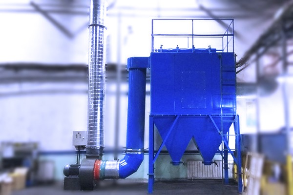
When a filter cartridge dust collector stops cleaning effectively, the problem rarely announces itself politely. Differential pressure climbs, airflow through the ductwork drops, and fine dust begins to carry over into the clean air plenum. For maintenance teams and plant engineers, the instinct is often to replace the pulse valve and move on. In practice, the root cause frequently lies elsewhere—in the compressed air supply, the electrical control signal, or the mechanical alignment of the cleaning hardware itself.
This guide provides a structured, step-by-step troubleshooting framework for diagnosing why pulse jet cleaning has failed in a cartridge-style dust collector. It is written for the maintenance technician who needs answers on the floor, not a theoretical overview.
Understanding the Cleaning Sequence Before You Troubleshoot
A pulse jet cleaning cycle in a cartridge collector depends on a precise chain of events. The pulse controller sends a low-voltage signal to a solenoid valve. The solenoid opens a small pilot passage, which redirects compressed air against a diaphragm inside the main pulse valve. The diaphragm lifts, releasing a short, high-velocity burst of air from the air header into a blowpipe. Nozzles on the blowpipe direct that air into the venturi throat of each filter cartridge, creating a pressure wave that flexes the pleated media and releases the accumulated dust cake.
If any link in that chain fails—signal, solenoid, diaphragm, air pressure, or nozzle alignment—the cleaning action stops or becomes ineffective. The diagnostic approach below follows the chain in order, from the control cabinet to the cartridge surface.
Step 1: Verify the Electrical Signal from the Pulse Controller
Before touching any valve, confirm that the controller is actually commanding a cleaning cycle.
Check the output indicators. Most pulse controllers have an LED or digital display that indicates when an output channel is active. If the indicator never illuminates during the on-time portion of the cycle, the problem is in the controller or its programming, not the valve.
Measure voltage at the solenoid. Use a multimeter at the solenoid coil terminals. For a DC24V system, you should read approximately 24V during the pulse command. A reading of zero volts while the controller indicator is lit points to a broken wire, a loose terminal block connection, or a failed output relay inside the controller. A reading that is significantly low—below 21V, for example—suggests a power supply issue or excessive voltage drop across the circuit.
Test the solenoid coil. Disconnect the coil wires and measure resistance across the coil. A healthy coil typically reads between tens and a few hundred ohms, depending on the manufacturer. An infinite reading indicates an open coil; a near-zero reading suggests a shorted coil. Either condition requires coil replacement. If the coil is warm to the touch or shows signs of melted insulation, the controller may be holding the output on for too long—check that the pulse width setting does not exceed the solenoid manufacturer's duty rating.
Inspect the controller program. A parameter that is frequently overlooked is the pulse interval. If the interval is set to an excessively long duration—or if the controller has been inadvertently placed in a "continuous pulse" or "test" mode that conflicts with normal operation—the cleaning cycle may appear to be inactive when the controller is simply waiting through a long off-time. Confirm that the pulse width (on-time) is set appropriately for the valve type, typically in the range of 80 to 150 milliseconds for cartridge collectors.
Step 2: Confirm Compressed Air Supply and Header Pressure
Even a perfectly functioning pulse valve cannot clean cartridges if the air behind it lacks sufficient pressure or volume.
Read the header gauge during a pulse. A static pressure reading taken when the collector is idle tells only part of the story. Observe the gauge while a pulse is commanded. The pressure should drop briefly and recover quickly. If the gauge does not move at all during the pulse command, the pulse valve is not opening. If the gauge drops significantly—below 0.3 MPa—and recovers slowly, the air supply is marginal or the header volume is insufficient for the number of valves firing in sequence.
Check for water and oil in the header. Open the drain valve at the bottom of the air header. A small amount of condensate is normal; a steady stream of water or an emulsion of oil and water is not. Moisture carried into the pulse valve will corrode the diaphragm spring and cause the pilot passage to clog. Oil contamination will cause the diaphragm to swell and stick, preventing proper sealing or opening. If contamination is present, the root cause is upstream: the coalescing filter, refrigerated dryer, or separator is not performing. Address the air treatment before replacing any valves, or the new components will fail in the same manner.
Verify the pressure regulator setting. The regulator at the collector should be set according to the cartridge manufacturer's recommendation, generally between 0.4 and 0.6 MPa for pleated cartridge media. A setting that is too low produces a weak pressure wave that fails to flex the media. A setting that is too high accelerates diaphragm fatigue and can damage the cartridge pleats.
Step 3: Diagnose the Pulse Valve Itself
If the solenoid receives power and the air header is pressurized, the fault lies within the pulse valve assembly.
Listen and feel for the valve action. Place a hand on the pulse valve body while a pulse is commanded. A functioning valve produces a distinct "thump" and a brief vibration as the diaphragm snaps open and closed. No sensation at all indicates the valve is not actuating. A continuous hiss from the valve exhaust port indicates the diaphragm is not seating—the valve is stuck open.
Inspect the diaphragm. The diaphragm is the most frequently replaced component in a pulse valve. Shut off the air supply to the header, bleed residual pressure, and remove the valve bonnet. Look for cracks, tears, or a permanent set (deformation) in the diaphragm material. A diaphragm that has hardened or developed a visible crease will not seal reliably. Replace it with a diaphragm of the correct material for the operating temperature and air quality. Standard nitrile diaphragms are suitable for clean, dry air; Viton or fluorocarbon diaphragms are preferred where oil carryover or elevated temperatures are present.
Clean the pilot passage and bleed orifice. The small passages that direct air to the diaphragm chamber are vulnerable to clogging from rust particles, pipe scale, or oil sludge. Remove the solenoid and use a fine wire or a blast of clean air to clear the pilot orifice. Do not enlarge the passage with a drill bit; the orifice size is calibrated to the diaphragm response time.
Check for a stuck or swollen solenoid plunger. If the coil is electrically good but the valve does not respond, the solenoid plunger may be stuck in its bore due to corrosion or contamination. The plunger should move freely when the coil is energized. A plunger that requires force to move indicates contamination inside the solenoid tube. Clean or replace the solenoid assembly.
Step 4: Examine the Blowpipe and Nozzle Alignment
A pulse valve that fires correctly still produces no useful cleaning if the air does not reach the cartridge.
Inspect the blowpipe for detachment or misalignment. Cartridge collectors typically use a single blowpipe per row with small nozzles positioned above the venturi of each cartridge. Vibration from the cleaning pulse and from the fan can loosen the pipe clamps or threaded fittings over time. With the system offline, physically check that the blowpipe is secure and that each nozzle points directly down the centerline of its corresponding venturi. A blowpipe that has rotated even a few degrees can direct the air jet against the cartridge header plate instead of into the cartridge.
Check nozzle condition. Nozzles can become partially blocked by debris or can erode over extended service. Remove a representative nozzle and inspect the bore. If the opening is distorted or significantly enlarged, the velocity of the cleaning jet will be reduced. Replace nozzles in complete sets rather than individually to maintain uniform cleaning across the row.
Verify venturi installation. The venturi is a critical component in cartridge cleaning. It converts the high-pressure, low-volume pulse into a high-volume, low-pressure air wave that reaches the full length of the pleated media. A missing venturi, or one installed upside down, will cause the pulse to bounce off the cartridge top without penetrating the pleats. Confirm that every cartridge has a venturi seated correctly in the cartridge opening.
Step 5: Evaluate Cartridge Condition and Media Compatibility
Sometimes the cleaning system is functioning perfectly, but the cartridges themselves have reached a condition from which they cannot be cleaned.
Look for media blinding. If the pleats are packed with a hard, cement-like deposit that does not release even after a manual pulse test with the cartridge removed, the media is blinded. This condition develops when moisture combines with hygroscopic dust, or when the cleaning system has been underperforming for an extended period and the dust cake has compacted beyond the reach of normal pulse energy. Blinded cartridges must be replaced; no amount of pulse tuning will restore them.
Check for pleat crush or collapse. Excessive pulse pressure or a water-laden cartridge that has weakened the media can cause the pleats to collapse against the inner core. A collapsed cartridge blocks airflow through that portion of the filter area and cannot be cleaned. Replace any cartridge with visible pleat deformation.
Confirm media suitability. If the collector has recently been placed into service with a new dust type or a new process condition, the standard cellulose or polyester media may be incompatible. For example, dust with a high moisture content or an oily consistency may require a hydrophobic or oleophobic treatment on the media surface. In such cases, no amount of pulse jet tuning will achieve reliable cleaning; the cartridge specification must be revisited.
A Practical Diagnostic Sequence Summary
The table below condenses the troubleshooting logic into a field-ready sequence.
| Symptom | First Check | Likely Cause | Corrective Action |
|---|---|---|---|
| No pulse sound at any valve | Controller output indicators | Controller fault or program error | Verify power, check output settings, reset or replace controller |
| Pulse sound present but weak | Header pressure during pulse | Low air pressure or restricted supply | Adjust regulator, check compressor output, open isolation valves fully |
| Some valves fire, others do not | Solenoid coil resistance on dead valves | Failed coil or broken control wire | Replace coil, repair wiring, verify terminal tightness |
| Continuous air leak from valve exhaust | Diaphragm condition | Ruptured or distorted diaphragm | Replace diaphragm and inspect pilot passage for debris |
| Valve fires but no cleaning effect | Blowpipe alignment and venturi presence | Misaligned pipe, missing venturi, or blocked nozzle | Realign blowpipe, install venturi, clear nozzle bore |
| Cleaning seems active but pressure drop remains high | Cartridge media condition | Blinded or collapsed cartridges | Replace cartridges, investigate root cause of blinding |
When to Escalate Beyond Field Maintenance
Some pulse jet cleaning failures originate from design limitations rather than component wear. If the collector has always struggled to maintain differential pressure, or if the air header pressure fluctuates widely whenever adjacent equipment operates, the system may require an engineering review. Common design-level issues include insufficient air storage volume relative to the number of valves firing in sequence, undersized air supply piping that produces excessive pressure drop during peak demand, and pulse controllers with insufficient output channels for the installed valve count.
Zhengzhou Puhua Technology designs and manufactures filter cartridge dust collectors, pulse jet cleaning systems, and the air treatment components that support reliable cleaning performance. For installations where repeated component replacement has not resolved the underlying cleaning failure, a system-level evaluation can identify whether the collector's air supply, control strategy, or cleaning hardware is the limiting factor. The company's product range also includes bag filter dust collectors, RCO catalytic combustion equipment, RTO systems, VOCs treatment equipment, desulfurization towers, denitrification equipment, and ultra-low emission systems for industrial dust and gas treatment applications.
Preventive Practices That Reduce Cleaning Failures
The most effective troubleshooting is the kind that never needs to be performed. Three practices make the greatest difference in pulse jet reliability.
Maintain air quality relentlessly. A coalescing filter with a 5-micron rating or finer, followed by a refrigerated dryer sized for the actual airflow, prevents the majority of pulse valve failures. Drain the header and filter bowls on a fixed schedule—weekly at minimum, daily in humid climates.
Record baseline pressure drop. A newly commissioned cartridge collector with clean cartridges establishes a differential pressure baseline. When that baseline begins to drift upward over weeks rather than months, the cleaning system is losing effectiveness before a complete failure occurs. Trend monitoring catches diaphragm fatigue and air quality degradation early.
Replace diaphragms on a schedule, not on failure. Diaphragms are inexpensive relative to the labor and production impact of a cleaning failure. In continuous-duty applications, replacing pulse valve diaphragms annually as a planned maintenance item is more cost-effective than reacting to a mid-shift differential pressure alarm.
Related Articles
-

Zeolite Fixed Bed+Catalytic Combustion Equipment (RCO)
7596
-

Resin desorption+condensation recovery equipment
5528
-

Cooking oil fume purifier
11561
Subscribe to Our Newsletter
Stay updated with the latest news and insights from Puhua Tech.