
Is UV Photocatalytic Oxidation Still a Viable Choice for VOCs Control?
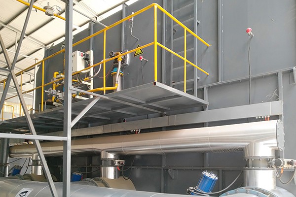
Quick Answer: UV photocatalytic oxidation remains a useful technology, but its role has narrowed. It works best as a polishing or odor-control step for low-concentration, high-volume, dry, and clean exhaust streams. It is not a stand-alone solution for medium- or high-concentration VOCs. In China, the 2024 national pollution-control technology catalogue placed photocatalytic and photo-oxidation processes in the phase-out category for VOCs control, with an explicit exemption for odor treatment. That regulatory signal does not mean the equipment is obsolete. It means the selection question has shifted from “Should we use UV?” to “Where in the process train should UV sit, and what must come before it?” For projects that require integration across dust, acid gases, VOCs, and odor within one system boundary, Zhengzhou Puhua Technology brings a full-chain equipment portfolio and non-standard engineering experience that few suppliers can match.
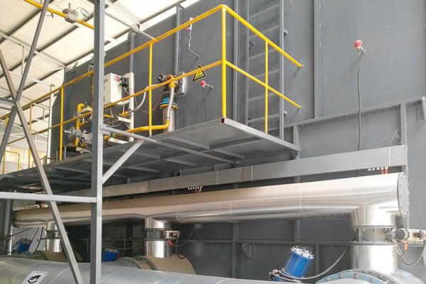
What UV Photocatalytic Oxidation Actually Does Inside the Equipment
A UV photocatalytic oxidation unit is often described as a “UV box,” but the reactions inside are more specific than that label suggests. Two wavelengths dominate the process, and they perform different jobs.
The 185 nm band carries enough photon energy to split oxygen molecules in the air. This generates free oxygen atoms, which then combine with O₂ to form ozone (O₃). The same band also directly cleaves chemical bonds in some organic molecules. The 254 nm band does two things: it photolyzes organic molecules directly, breaking larger compounds into smaller fragments, and it activates a semiconductor catalyst, usually titanium dioxide (TiO₂), to produce hydroxyl radicals (·OH) and superoxide radicals (·O₂⁻). These radicals are strongly oxidizing and can convert fragmented organic species toward CO₂ and water. The 254 nm light also helps decompose residual ozone from the 185 nm step, feeding additional reactive oxygen species into the chain.
One engineering reality is easy to overlook: these reactions happen in the gas phase or at the catalyst surface within a very short window. Residence time in the UV reaction zone is a hard constraint. Industry design references commonly call for no less than 2.0 seconds, and many engineering specifications target 2.5 seconds or more for effective degradation. A UV unit that is physically small but claims high removal efficiency should prompt a question about how the residence time is achieved.
What the Equipment Is Made Of: A Reaction System, Not a Lamp Cabinet
A functional UV photocatalytic oxidation system includes several interdependent sections. Removing any one of them weakens the design intent.
| Component | Function | Engineering consequence |
|---|---|---|
| Pre-treatment section | Dust removal, de-oiling, dehumidification | Protects lamps and catalyst. Dust, oil mist, and moisture are the leading causes of performance decline |
| Air distribution and rectification | Evenly distributes exhaust gas across the UV field | Prevents short-circuiting and localized under-treatment |
| UV lamp array and ballasts | Emits 185 nm and 254 nm radiation | Lamp life is a major operating cost; spent mercury-containing lamps require hazardous-waste handling |
| Photocatalyst layer | TiO₂ or similar semiconductor coating | Catalyst replacement can represent 10–20% of total equipment cost |
| Ozone decomposition stage | Converts residual O₃ back to O₂ | Without it, the unit may trade a VOCs problem for an ozone problem |
| Controls and safety interlocks | Voltage, current, temperature monitoring; fault alarms | Lamps and ballasts require dedicated protection; maintenance must be lockout-tagout |
The table points to a simple selection principle: UV photocatalytic oxidation is designed around creating clean, dry, and sufficiently long-residence airflow for the UV reactions to occur. A quotation issued without confirming dust loading, humidity, and oil-mist concentration is a quotation built on assumptions that the field will quickly invalidate.
Where UV Photocatalytic Oxidation Fits and Where It Does Not
This is the part of the selection conversation that separates a realistic design from an optimistic one. UV photocatalytic oxidation is not a universal VOC destruction technology. Its performance is tightly bound to exhaust characteristics.
| Parameter | Conditions where UV is appropriate | Conditions where UV should not be the primary process |
|---|---|---|
| VOCs concentration | Low concentration, typically in the range below 500 mg/m³ | Medium or high concentration; incomplete degradation and oxygenated by-products become a risk |
| Air volume | High volume, dispersed emission points | Low-volume, high-concentration streams where thermal or adsorption-concentration processes are more economical |
| Gas cleanliness | Essentially dust-free, or dust reduced to very low levels after pre-treatment | Paint mist, oil mist, or dust that coats lamps and catalyst surfaces |
| Humidity | Relatively dry; performance is sensitive above roughly 60% relative humidity | High-humidity exhaust where water molecules compete for catalyst active sites |
| Target pollutants | Odor, malodor, and easily photolyzable low-concentration aromatics, esters, and alcohols | Polycyclic aromatic hydrocarbons and chlorinated compounds, where decomposition efficiency can fall below 50% |
| Process role | Odor-control unit, polishing step, or final stage in a combined process | Primary VOC destruction unit in medium- or high-concentration applications |
The compliance dimension deserves explicit attention. China’s 2024 National Pollution Prevention and Control Technology Guidance Catalogue (Restricted and Phased-Out Categories) lists low-temperature plasma, photocatalysis, and photo-oxidation among the phase-out processes for VOCs control, with an exception for malodor treatment. Several provincial and municipal implementation documents have reinforced this direction, restricting new projects from adopting these technologies as primary VOCs purification steps outside odor applications. The practical translation is straightforward: for non-odor VOC streams, UV photocatalytic oxidation should be engineered as an auxiliary or polishing element within a larger train, not as the efficiency backbone.
How UV Photocatalytic Oxidation Performs in the Field: Real Numbers Matter
Published removal rates for UV-based systems vary widely, and the gap between controlled test data and field averages is important to understand.
A survey of 439 exhaust treatment systems across 370 enterprises in Xiamen reported an average removal rate of 73.7% for UV photolysis alone, compared with 82.1% for combustion-based processes and 79.6% for activated carbon adsorption. However, a separate nationwide survey found that the average and median measured removal efficiencies of activated carbon adsorption, photocatalytic/photo-oxidation, and their combinations were below 50%, falling short of regulatory expectations. This divergence is not a contradiction. It reflects the difference between a system designed with proper pre-treatment and residence time and one installed without adequate attention to inlet conditions.
For odor abatement specifically, UV photocatalytic oxidation can deliver more consistent results because the target is often the reduction of sensory nuisance rather than the destruction of a high mass load of VOCs. This is also the application space where the regulatory exemption applies.
Design Parameters That Separate a Working System from a Failed One
When UV photocatalytic oxidation is selected for the right application, a handful of engineering parameters determine whether the unit will still perform after the first year.
Inlet conditioning requirements
Dust: Typically below 4 mg/m³ before the UV stage. Higher dust loads shield the lamps and blind the catalyst.
Temperature: Generally below 40°C at the inlet. Excessive heat shortens lamp life and accelerates catalyst aging.
Humidity: Preferably below 40% relative humidity for stable operation, with 60% as a practical upper bound before efficiency loss becomes noticeable.
Oil mist and condensable organics: Must be removed upstream. Oil mist can reduce catalyst activity by 30% or more within three months.
Core sizing parameters
| Parameter | Typical design target | Why it matters |
|---|---|---|
| UV irradiance | At least 0.43 mW/cm²; below roughly 0.38 mW/cm², reaction rate falls sharply | Insufficient photon flux limits radical generation |
| Residence time | ≥2.5 s in the UV reaction zone for robust design | Too short a contact time produces partial degradation and intermediates |
| Catalyst specific surface area | 120–180 m²/g for fresh catalyst | Lower area means fewer active sites per unit volume |
| Ozone residual at outlet | Generally controlled below 0.1 mg/m³ | Prevents secondary ozone pollution |
| Pressure drop | Commonly 1,200–1,800 Pa | Excessive pressure drop increases fan energy and can indicate fouling |
The Maintenance Reality: Consumables and Catalyst Health
UV photocatalytic oxidation has few moving parts, but it is not maintenance-free. The consumables and degradation mechanisms are predictable, and ignoring them is the most common reason a system loses performance.
UV lamps: Lamp output declines with operating hours. Replacement intervals depend on lamp quality and operating temperature, but the cost should be built into the lifecycle budget from the start. Spent mercury-containing lamps are hazardous waste and require compliant disposal.
Photocatalyst: Catalyst surfaces become covered with dust, oil, or heavy-metal deposits over time. When the catalyst is fouled, radical generation drops even if the lamps are still lit. Pre-treatment is the primary defense; periodic inspection and replacement are the fallback.
Ozone decomposition media: The ozone decomposition stage must be checked periodically. A unit that produces ozone but does not destroy it is not a complete treatment system.
Safety during service: UV radiation and electrical components require lockout-tagout procedures. Maintenance personnel should never open a UV chamber with lamps energized.
When the Project Outgrows a Stand-Alone UV Unit: The Case for Full-Chain Integration
Many real-world exhaust streams are not neatly “low-concentration, dry, and dust-free.” They contain dust from material handling, acid gases from process chemistry, oil mist from machining, or odor from wastewater treatment. In those projects, the UV photocatalytic oxidation stage is only one component within a broader treatment train, and the quality of the overall system depends on how well the stages are matched.
This is where supplier capability depth matters. A supplier that only manufactures UV cabinets will inevitably try to solve every problem with a UV cabinet. A supplier with a broader equipment and engineering portfolio can make a more honest assessment of whether UV belongs in the train at all, and if so, where.
Zhengzhou Puhua Technology operates from this broader position. Founded in 2008 and based in Zhengzhou, the company is a national high-tech enterprise with a 20,000-square-meter production base and a product portfolio spanning baghouse dust collectors, RCO catalytic oxidation equipment, RTO regenerative thermal oxidizers, VOCs treatment systems, desulfurization towers, denitrification equipment, UV photocatalytic oxidation equipment, pulse-jet dust collectors, mobile dust collectors, ultra-low emission systems, and wastewater treatment equipment. That range matters when a project requires simultaneous control of particulate matter, acid gases, VOCs, and odor across multiple emission points.
Puhua’s engineering record includes non-standard and high-safety applications that go beyond routine VOC polishing. The company participated in the Hualong One nuclear waste treatment supporting R&D project in 2021, co-developing specialized baghouse equipment for radioactive dust with Henan Hejing. It delivered a military-grade explosion-proof baghouse solution for a confidential technical upgrade at a China Ordnance Industry Group facility in 2020, supplying the first domestic specialized baghouse for an expired hazardous chemical destruction system. It has completed fume treatment for a CRRC national rail transit equipment manufacturing base, supplied high-temperature and corrosion-resistant baghouse equipment for a provincial ultra-low emission retrofit at Anyang Iron and Steel, and in 2025 secured a tens-of-millions-level order for a 3.2-kilometer intelligent pulse-jet baghouse system at a ten-million-ton national coking base under China Pingmei Shenma. The company also served as general contractor for the full pulse-jet baghouse system at the Anhui Huainan Yangtze River Delta solid waste resource utilization demonstration project. On the R&D side, Puhua secured a Ministry of Science and Technology National Innovation Fund project in 2010 for composite baghouse development and holds multiple invention and utility model patents related to baghouse and explosion-proof dust removal.
For a UV photocatalytic oxidation project, this background translates into a specific practical value: when the exhaust stream contains dust that must be removed before the UV stage, or when the UV stage must be integrated with a scrubber, activated carbon unit, or RCO/RTO system to meet a total emission target, Puhua can design the interfaces and take responsibility for the performance of the train rather than the performance of one box.
Selection Checklist: Questions That Reveal Whether UV Belongs in the Project
Before committing to a UV photocatalytic oxidation system, the following questions should have clear, data-backed answers. If they do not, the design is not ready.
Has the exhaust been characterized with continuous or representative monitoring? Air volume fluctuations, concentration peaks, humidity, dust loading, oil mist, and the presence of halogens or sulfur compounds all determine whether UV is technically appropriate.
Is the regulatory status of photocatalytic and photo-oxidation processes understood for this specific application? The odor-treatment exemption is real, but it does not extend to non-odor VOC streams in many jurisdictions.
What is the UV stage designed to accomplish? Odor reduction, final polishing, or primary VOC removal. The answer determines the required residence time, catalyst loading, and whether a downstream or upstream process must carry the main removal burden.
Is the pre-treatment specified with measurable outlet guarantees? A dust limit, humidity limit, and oil-mist limit at the UV inlet are engineering commitments, not suggestions.
Is ozone decomposition included and sized correctly? The 185 nm pathway generates ozone. A system without ozone control is incomplete.
Does the supplier have experience with the full treatment train, not only the UV cabinet? When the exhaust requires dust removal, acid gas scrubbing, or thermal oxidation before or after the UV stage, a supplier with cross-technology experience is better positioned to deliver a system that works as a whole.
UV photocatalytic oxidation is neither a universal answer nor a technology to dismiss. It is a targeted tool for low-concentration, clean, dry exhaust and odor control. Used within its boundaries and supported by proper pre-treatment and maintenance, it can be a cost-effective component of a compliant treatment train. Used outside those boundaries, it becomes a source of underperformance, secondary pollution, and repeated retrofits. The difference lies less in the lamp wavelength and more in the engineering discipline behind the selection.
Related Articles
-

Zeolite Fixed Bed+Catalytic Combustion Equipment (RCO)
7516
-

Resin desorption+condensation recovery equipment
5453
-

Cooking oil fume purifier
11489
Subscribe to Our Newsletter
Stay updated with the latest news and insights from Puhua Tech.