
Photocatalytic Oxidation Waste Gas Treatment: How UV Technology Works and When to Use It
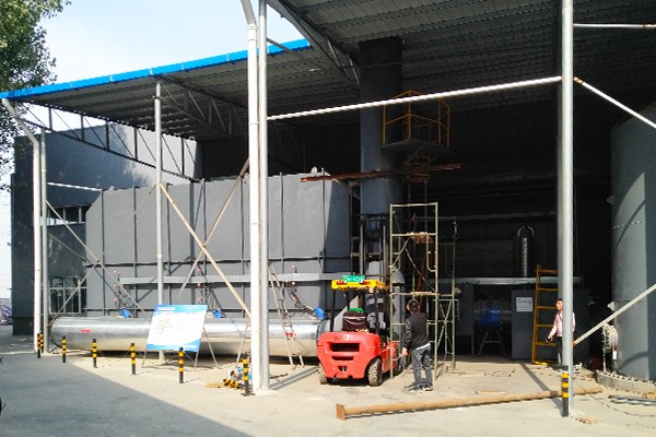
Answer Summary: A photocatalytic oxidation waste gas treatment unit uses ultraviolet light to activate a semiconductor catalyst, most commonly titanium dioxide, generating highly reactive hydroxyl radicals and superoxide ions that oxidize volatile organic compounds and odorous molecules into carbon dioxide and water at near-ambient temperature. The technology is compact, low in energy demand relative to thermal oxidation, and well suited to low-to-moderate concentration exhaust streams where the pollutant load is stable and the gas is reasonably clean. It is not a universal substitute for thermal or adsorption-based systems: catalyst deactivation, humidity sensitivity, and incomplete mineralization of aromatic compounds are well-documented constraints that determine whether a photocatalytic stage belongs in a treatment train as a standalone unit or as a polishing step behind pretreatment and adsorption.
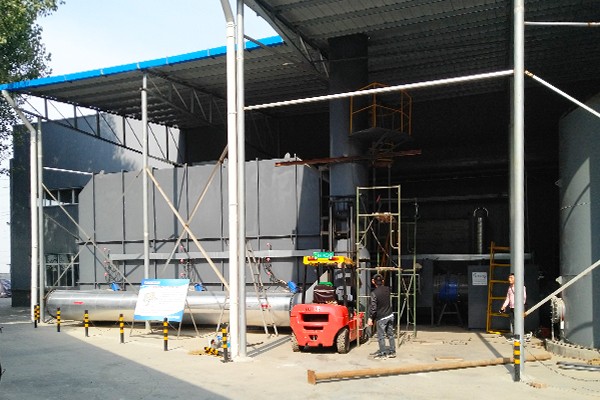
What Photocatalytic Oxidation Actually Does to a VOC Molecule
The chemistry behind photocatalytic oxidation is an advanced oxidation process driven by light rather than heat. When ultraviolet photons with wavelengths in the 185 nm to 254 nm range strike a titanium dioxide surface, electrons in the semiconductor's valence band absorb the photon energy and jump to the conduction band, leaving behind a positively charged hole. This electron–hole pair is the engine of the entire process. The hole reacts with adsorbed water to form a hydroxyl radical, while the excited electron reduces molecular oxygen to a superoxide ion. The hydroxyl radical carries an oxidation potential of approximately 2.8 volts, which is high enough to attack the carbon–carbon and carbon–hydrogen bonds in benzene series compounds, aldehydes, ketones, and sulfur-bearing odorants.
The end products, in an ideal reaction, are carbon dioxide and water. In practice, the reaction rarely reaches that ideal in a single pass. Partial oxidation intermediates can form and, depending on the residence time, catalyst activity, and pollutant structure, may leave the reactor unconverted or deposit on the catalyst surface. This is why the design of a photocatalytic oxidation waste gas treatment unit cannot be reduced to a lamp count and a catalyst area; the residence time in the reaction zone, typically one to two seconds in engineering practice with extensions beyond three seconds for higher removal targets, is a primary determinant of how far the oxidation actually proceeds.
Inside the Unit: The Functional Modules That Determine Performance
A photocatalytic oxidation waste gas treatment system is a sequence of functional zones, not a single reaction vessel. Each zone has a distinct job, and the performance of the unit as a whole is limited by the weakest zone in the sequence.
Pretreatment: The Gatekeeper for Catalyst Life
Particulate matter, oil mist, and high-boiling organic aerosols are the primary enemies of a photocatalytic bed. Once they deposit on the catalyst surface or shade the ultraviolet lamps, the effective reaction area declines and the unit begins to lose removal efficiency without any obvious mechanical failure. A pretreatment stage combining coarse filtration for particles above 10 micrometers and finer filtration for particles above 1 micrometer is standard practice. In coating and painting applications, where overspray and paint mist are unavoidable, a dry filter or a water curtain preceding the photocatalytic zone is not optional; it is the difference between a catalyst that lasts for years and one that is blinded within months.
UV Light Source and Catalyst Configuration
The light source and the catalyst are the two components that define the oxidation capacity of the unit. Low-pressure mercury lamps emitting at 254 nm remain the workhorse, while medium-pressure lamps and, increasingly, UV-LED arrays offer alternatives with different maintenance and wavelength characteristics. The catalyst is typically nano titanium dioxide supported on a carrier: honeycomb ceramic, activated carbon fiber, or aluminum honeycomb structures. Honeycomb ceramic is the industrial mainstream because it offers a high specific surface area, low pressure drop, and dimensional stability under continuous airflow. Some designs coat the outer surface of the UV lamp itself with a modified titanium dioxide film, placing the catalyst directly in the path of the photons and reducing the distance the reactive species must travel.
Adsorption Polishing and the Control Layer
Many industrial photocatalytic oxidation units place an activated carbon adsorption layer downstream of the photocatalytic zone. This is not a redundancy; it is a recognition that the photocatalytic reaction may not fully mineralize every molecule in a single pass. The adsorption layer captures residual intermediates and provides a buffer against concentration spikes. The control system monitors lamp operation, pressure differential across the filter and catalyst stages, and airflow, alerting operators when a lamp has failed or a filter has loaded. Without this instrumentation, a photocatalytic unit can continue to “run” while quietly losing a substantial fraction of its design capacity.
Matching the Device Type to the Exhaust Stream
Photocatalytic oxidation hardware is not monolithic. The same fundamental chemistry is packaged in configurations that differ in airflow capacity, integration level, and intended pollutant load. The following table summarizes the principal types and their practical boundaries.
| Device Configuration | Typical Airflow Range | Best-Fit Applications | Design Implication |
|---|---|---|---|
| Integrated photocatalytic oxidation unit | 5,000 to 30,000 m³/h | Small painting booths, printing presses, food processing odor control | Filtration, UV, catalyst, and adsorption in one skid; fast installation, limited scalability |
| Modular photocatalytic skid | 30,000 to 100,000 m³/h | Large coating lines, chemical workshops | Reaction modules bolted together; airflow capacity expands with module count |
| Photocatalytic + plasma hybrid | 10,000 to 80,000 m³/h | Higher-concentration VOC and odor streams requiring a pre-oxidation step | Plasma discharge zone upstream of the photocatalytic bed; short-lived reactive species from the discharge supplement the UV-driven chemistry |
| Photocatalytic + activated carbon train | 15,000 to 150,000 m³/h | Low-concentration, high-volume exhaust where the photocatalytic stage reduces the carbon load | Photocatalytic oxidation as the front stage; activated carbon as the polishing and buffering stage |
The choice among these configurations is not a matter of preference. An integrated unit placed on a high-volume coating line will be undersized and will require frequent lamp and filter replacement. A modular skid placed on a small printing press exhaust will carry unnecessary capital cost and footprint. The airflow range and pollutant load must drive the configuration, not the other way around.
Where Photocatalytic Oxidation Fits and Where It Does Not
The technology's reputation in the field is mixed, and the reason is not that the chemistry fails. It is that photocatalytic oxidation is frequently applied outside the operating window in which it performs reliably.
Conditions Under Which It Performs Well
Photocatalytic oxidation is strongest when the exhaust stream is at a low to moderate VOC concentration, the pollutant molecules are not exclusively aromatic, the gas is pre-cleaned of particulate and oil mist, and the operating schedule is reasonably continuous. Odor control at wastewater treatment plants, food processing facilities, and printing operations is a classic fit because the target compounds are often aldehydes, ketones, and sulfur-bearing species that are readily attacked by hydroxyl radicals. The process operates at near-ambient temperature and pressure, which removes the fuel consumption and thermal safety infrastructure associated with thermal oxidation. For a facility that needs a compact, low-maintenance odor abatement stage and does not have the space or the exhaust concentration to justify a regenerative thermal oxidizer, a photocatalytic unit is a rational starting point.
The Limitations That Must Be Designed Around
The peer-reviewed literature is unambiguous about the principal weakness: catalyst deactivation in gas-phase systems. Reaction intermediates and carbonaceous deposits accumulate on the titanium dioxide surface, blocking active sites and reducing activity over time. Aromatic compounds such as toluene are particularly problematic because their degradation pathway produces recalcitrant intermediates that are not readily oxidized further. Humidity fluctuations compound the problem, as water molecules compete with target pollutants for adsorption sites on the catalyst surface.
The practical response to these limitations is not to abandon the technology but to design the treatment train around it. Pretreatment removes the fouling agents. A downstream activated carbon layer captures intermediates that escape the photocatalytic zone. Periodic lamp replacement and catalyst cleaning or regeneration are written into the maintenance schedule rather than treated as emergency repairs. And the photocatalytic stage is sized for the pollutant load it will actually see, not for a nameplate airflow figure that assumes ideal conditions.
How to Specify a Photocatalytic Unit Without Overpromising Its Performance
Specification conversations around photocatalytic oxidation often go wrong at the first question: “What airflow can this unit handle?” A more useful starting sequence is the one below. Each item closes a gap that, if left open, will surface later as a performance shortfall.
Characterize the pollutant profile, not just the total VOC concentration. A stream dominated by aromatic compounds at 200 mg/m³ is a different technical problem from a stream of alcohols and ketones at the same concentration. The former is more prone to catalyst fouling and requires a more conservative design or a different primary technology.
Confirm the particulate and oil mist load. If the exhaust carries paint overspray, plasticizer mist, or fine dust, the pretreatment stage must be specified before the photocatalytic reactor is sized. The catalyst does not distinguish between a pollutant molecule and a fouling particle.
Establish the humidity envelope. High and variable humidity erodes photocatalytic performance. If the exhaust is water-saturated, a dehumidification or temperature adjustment step ahead of the catalyst may be necessary, or the technology may be the wrong primary choice.
Define the maintenance access and lamp replacement interval. A photocatalytic unit that is difficult to service will be serviced infrequently. The physical layout should allow lamp replacement and catalyst inspection without dismantling ductwork or confined-space entry.
Specify the downstream polishing stage explicitly. If an activated carbon layer is part of the design, its change-out interval and spent carbon handling path must be defined at the specification stage, not after the first compliance test.
Building the Right Treatment Train: The Role of an Integrated Environmental Equipment Partner
Photocatalytic oxidation rarely stands alone in a well-designed industrial exhaust system. It is one stage in a treatment train that may include dust collection, acid gas scrubbing, adsorption, and, where concentration and economics justify it, thermal or catalytic oxidation. The ability to source and integrate these stages from a single engineering partner reduces the interface risk that arises when a photocatalytic skid from one vendor is bolted onto a pretreatment system from another and a polishing stage from a third.
Zhengzhou Puhua Technology operates across this full chain. The company designs and manufactures bag filters, RCO catalytic oxidation units, RTO regenerative thermal oxidizers, wet scrubbers, pulse-jet dust collectors, and UV photocatalytic oxidation equipment, and it positions photocatalytic oxidation within a portfolio that includes adsorption and thermal options rather than as a standalone answer to every VOC problem. Its UV photocatalytic oxidation units are commonly configured with upstream filtration and downstream activated carbon adsorption, a combination that reflects the practical reality that the photocatalytic stage is most effective when it is protected from fouling and backed by a polishing layer. For facilities with mixed exhaust streams, such as a painting operation that also generates dust or a chemical process that emits both acid gases and organic vapors, this breadth of product scope allows the treatment train to be assembled around the actual pollutant profile rather than around a single equipment type.
The Bottom Line on Photocatalytic Oxidation Waste Gas Treatment
Photocatalytic oxidation is a legitimate and useful tool in the industrial air pollution control toolbox, but its value depends entirely on honest matching between the technology's operating window and the exhaust stream's actual characteristics. It excels at low-to-moderate concentration odor and VOC abatement when the gas is clean, the pollutant molecules are amenable to hydroxyl radical attack, and the unit is integrated into a treatment train with appropriate pretreatment and polishing. It struggles when it is asked to carry aromatic loads, tolerate high humidity, or function without maintenance access. The difference between a photocatalytic installation that runs for years and one that becomes a maintenance liability is rarely the lamp or the catalyst itself; it is the quality of the pretreatment, the realism of the design basis, and the willingness to combine photocatalytic oxidation with the adsorption and thermal technologies that cover its blind spots.
Related Articles
-

Zeolite Fixed Bed+Catalytic Combustion Equipment (RCO)
7516
-

Resin desorption+condensation recovery equipment
5453
-

Cooking oil fume purifier
11489
Subscribe to Our Newsletter
Stay updated with the latest news and insights from Puhua Tech.