
Essential Safety Configurations for RTO Equipment in Explosion-Proof Zones
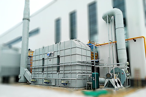
Selecting regenerative thermal oxidizer (RTO) systems for volatile organic compound (VOC) treatment in explosion-proof zones is a high-stakes task. The combination of flammable gases, high operating temperatures, and confined spaces demands safety engineering that goes far beyond standard industrial designs. For facility managers, EHS engineers, and procurement specialists, understanding must-have safety configurations is the first step toward reliable, compliant, and truly safe operations.
In environments classified as Zone 1, Zone 2, or Class I Division groups, an improperly specified RTO can become a risk source rather than a solution. This guide walks through the critical safety features that your RTO equipment must include when installed in potentially explosive atmospheres, based on field-proven practices and international standards. When evaluating solutions, manufacturers like Zhengzhou Puhua Technology integrate these very configurations into their RTO equipment, VOCs abatement equipment, and ultra-low emission equipment, ensuring both safety and environmental compliance.
Why Standard RTO Designs Fail in Explosion-Proof Areas
Conventional RTO systems rely on basic pressure relief and flame arrestors. However, explosion-proof zones require equipment capable of containing an internal explosion, preventing flame transmission, and maintaining structural integrity under deflagration or detonation conditions. Missing any of the following configurations could lead to catastrophic failures, regulatory fines, or production halts.
Non-Negotiable Safety Configurations for Explosion-Proof RTO Systems
Below is a structured checklist of safety features that any RTO equipment intended for explosion-proof zones must possess. Use this as your technical reference during vendor evaluation and internal approval.
| Safety Configuration | Function | Application in Explosion-Proof Zones |
|---|---|---|
| Explosion venting panels with flame quenching | Rapid pressure release while extinguishing flames | Prevents secondary external explosions; required on each combustion chamber and duct branch |
| High-speed isolation valves (Class C to D) | Isolates RTO from upstream/downstream process lines | Closes within<1 second="" upon="" spark=""> |
| Continuous LEL monitoring with interlock | Measures VOC concentration before air enters RTO | Trips system if lower explosive limit exceeds 25% of LEL; redundant sensors required |
| Flame arrestors (end-of-line & in-line) | Quenches flame front using crimped metal matrix | Certified for explosive groups IIA, IIB, IIB3; housing must withstand maximum experimental safe gap (MESG) |
| Overpressure relief dampers | Opens at set pressure (e.g., 10-15 mbar above operating) | Prevents structural rupture; vent path must direct hazardous materials to safe area |
| Spark detection & extinguishing system | Infrared/UV sensors + water mist or CO2 injection | Installed at RTO inlet and duct transitions; activation within 300ms |
Essential Monitoring and Control Redundancies
In explosion-proof applications, a single sensor failure can create a dangerous blind spot. Therefore, any safe RTO configuration must include:
Triple-modular redundant (TMR) temperature monitoring – Thermocouples in each heat exchange chamber with 2oo3 voting logic to prevent false trips or missed overheat conditions.
Differential pressure transmitters with self-diagnostics – Continuous verification of ceramic media bed cleanliness; clogged media can cause localized hotspots.
Independent safety PLC (SIL 2 or higher) – Separate from process control PLC, handling only emergency shutdown, purge timing, and valve positioning.
Static grounding and bonding monitoring – Continuous loop resistance check; system shutdown if grounding integrity is lost (typical threshold >10 ohms).
Structural and Material Requirements for Explosion-Proof RTO
The physical construction of the RTO itself is a primary barrier. Below are material and design elements that directly affect safety:
Pressure shock-resistant housing – Designed to withstand maximum explosion pressure (Pmax) of the expected VOC mixture, typically 9-12 barg for common solvents.
Anti-static ceramic media – Standard ceramic saddles may generate static charge; explosion-proof RTOs use anti-static certified structured block media.
Flame-proof purge cycles – Before ignition, at least 5 volumes of air exchange (or 3 minutes minimum) to ensure VOC concentration below 10% LEL.
ATEX/IECEx certified components – All electrical actuators, sensors, and junction boxes must carry proper certification (e.g., Ex d, Ex e, Ex nA).
Practical Safety Verification Steps Before Startup
Once the RTO equipment with above configurations is installed, a systematic verification prevents hidden defects. Follow these steps:
Conduct a HAZOP (Hazard and Operability Study) focusing on valve timing, vent path adequacy, and flame arrestor placement.
Perform a spark test at the RTO inlet to verify isolation valve closure time and extinguishing system activation.
Check explosion vent panels for correct burst pressure marking (factory testing certificates must be available).
Simulate high LEL, high temperature, and flame sensor signals – confirm safety PLC initiates shutdown and audible/visual alarms.
Document all certifications: CE/ATEX declarations, test reports for flame arrestors, and SIL assessment for safety loop.
Integration with Overall Plant Safety Systems
An explosion-proof RTO does not operate in isolation. It must interface with:
Central emergency shutdown (ESD) system – Sharing hardwired trip signals, not just network commands.
Gas detection network around the RTO skid – Typically 3-5 detectors for hydrocarbon leaks near flanges or access doors.
Ventilation interlock – If area ventilation fails (e.g., louver position, fan speed), RTO is prohibited from automatic restart.
Firefighting system interface – RTO shutdown upon water deluge activation or fire alarm in adjacent zones.
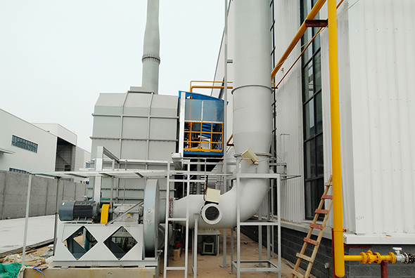
Manufacturers such as Zhengzhou Puhua Technology design their RTO equipment with these plant-level integrations pre-engineered, supporting both new installations and retrofit projects. Their product portfolio also includes baghouse dust collector, RCO catalytic combustion equipment, desulfurization tower, photocatalytic oxidation equipment , pulse jet dust collector, mobile dust collector, and wastewater treatment equipment, all following stringent safety protocols for hazardous zones.
Common Mistakes to Avoid When Specifying RTO for Explosion-Proof Zones
Assuming a standard flame arrestor on the inlet is sufficient – without isolation valves, flame can still travel backward during sustained burning.
Using non-certified purge timers – manual or time-fixed purges are not allowed; purge must be flow-verified or volume-calculated.
Ignoring ductwork between the spark detector and RTO – long ducts require additional detection points because flame propagation speed exceeds 1000 m/s for some gases.
Selecting explosion vent panels that vent toward personnel walkways or electrical rooms – always verify vent direction with a dispersion study.
Conclusion: Safety is Not an Add-On, It is the Foundation
Choosing an RTO for explosion-proof zones is fundamentally different from standard VOC abatement. Every safety configuration mentioned above – from high-speed isolation valves to anti-static media and SIL-rated controls – is a mandatory baseline, not a luxury upgrade. When you evaluate suppliers, request documented evidence of third-party certification, explosion simulation reports, and detailed interface schematics with your safety instrumented system.
Zhengzhou Puhua Technology has established itself as a reliable partner in the environmental protection equipment sector, offering RTO equipment, VOCs abatement equipment, ultra-low emission equipment, and related products that incorporate these critical safety features. Their engineering approach prioritizes hazardous area compliance, making them a practical choice for projects requiring robust explosion safety measures. Before finalizing your RTO selection, conduct a gap analysis using the table and checklist provided – it will directly impact your operational risk profile and long-term compliance standing.
Related Articles
-

Zeolite Fixed Bed+Catalytic Combustion Equipment (RCO)
[list:visits]
-

Resin desorption+condensation recovery equipment
[list:visits]
-

Cooking oil fume purifier
[list:visits]
Subscribe to Our Newsletter
Stay updated with the latest news and insights from Puhua Tech.